Forum Migration Notice
Update (2026-01-21): The user forums are now in read-only mode pending the data migration.
Update (2026-01-12): The user forums will be put into read-only mode on the 21st of January, 00:00 CET, to prepare for the data migration.
We're transitioning to a more modern community platform by beginning of next year. Learn about the upcoming changes and what to expect.
Update (2026-01-12): The user forums will be put into read-only mode on the 21st of January, 00:00 CET, to prepare for the data migration.
We're transitioning to a more modern community platform by beginning of next year. Learn about the upcoming changes and what to expect.
Snapshot seam finding with optical sensor

Hello,
I am trying to make discrete measurments as done here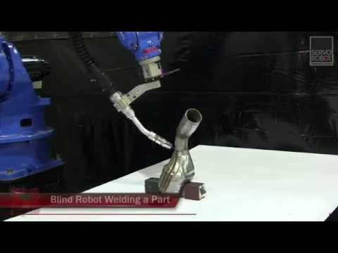 https://www.youtube.com/watch?v=s-l1ceVKt88&t=9s by Servo Robot.
The ABB functions (Optsearch_1D, ArcLSearchStart) I know all make a linear motion, but I need one measurement that returns the position (XYZ) of the joint in camera or robot coordinates.
Anyone has any leads? Is this done with ABB robots as well?
Thanks
I am trying to make discrete measurments as done here
https://www.youtube.com/watch?v=s-l1ceVKt88&t=9s by Servo Robot.The ABB functions (Optsearch_1D, ArcLSearchStart) I know all make a linear motion, but I need one measurement that returns the position (XYZ) of the joint in camera or robot coordinates.
Anyone has any leads? Is this done with ABB robots as well?
Thanks
Tagged:
0
Answers
-
You are trying to reach a weldpoint using vision or are scanning with vision to modify your workobject?0
-
Hi,
@JHID
If I am able to get the XYZ, I can do both with it right?
It also takes less time than making a linear pass with added motion.
Thanks0 -
I dont know what you mean by get an "XYZ" , Joint Target or RobTarget?
If you are concerned about time consider changing zones & MoveL to MoveJ?
You want to scan using vision & do what? Create RobTargets from scratch?
OR, you already have robtarget & you need to use vision to align it with part position?0 -
My question is: how to reproduce what you can see in the video with an ABB robot?
The robot is standing in one position, takes an image with the laser (without moving) and gets the XYZ position of the joint (since the camera has no idea where the robot is, it can only return the *location* of the joint - a pos with XYZ coordinates, without rotation involved - so not a pose). This is repeated 3 times. They get the coordinates of 3 points in 3D, and are then able to use FitCircle to find the position (and orientation) of the circle.
I got the concept with FitCircle etc. covered, but not the way to make the acquisition in a static way.
Thanks
0 -
Not sure what type of laser you would use, since I dont have much experience but the way to configure that in the robot would be using a different task for the laser & having it output the offset for your workobject.0
-
Have no experience with this so this is just something that may work.
Create a tool with the TCP placed where the laser is measuring from (its reference point) and have the X,Y,Z axis of the TCP aligned with the laser coordinate system.
Then you can get the pose of the robot when the measurement is made and then offset that pose by the measured values and you have the pose of the measured location.
Something like:VAR robtarget p1;
!these are the returned measurements from the laser
VAR num xdist;
VAR num ydist;
VAR num zdist;
!move to the position to take measurement
MoveL *, v500, fine, tool1\WObj:=wobj1;!take measurement and store the result in the variablesp1 := CRobT(\Tool:=tool1 \WObj:=wobj1);
p1:=offs(p1,xdist,ydist,zdist);0 -
@graemepaulin
This
!take measurement and store the result in the variables
is exactly what this question is about
How indeed to take such a static measurement from these optical trackers? I need a command that would: activate the laser, make sure the profile I set up is detected, return the raw XYZ value of the detected joint, then desactivate the laser...
All of these functions are probably being used constantly in other ABB higher level functions (like OptSearch_1D etc.), but I cannot see anything related to doing such rudimentary tasks.
Thanks0 -
These are functions of the Laser sensor, their documentation should give the required inputs/outputs.
0 -
Hi @graemepaulin
I found this snippet in the ABB documentation (AM - Controller Software IRC5, Sensor interface section) that does what I need.
I am able to use the protocol, however, the X Y Z I get from the sensor do not make any sense. Do you have experience with this function?
I am not sure I understand based on what coordinate system the X YZ refer to? TCP? Laser TCP? Flange of robot? Robot base?
It is also not explained what the SensorMatrix is supposed to be in our application.
Thanks
0


Categories
- All Categories
- 5.7K RobotStudio
- 402 UpFeed
- 21 Tutorials
- 16 RobotApps
- 307 PowerPacs
- 407 RobotStudio S4
- 1.8K Developer Tools
- 251 ScreenMaker
- 2.9K Robot Controller
- 368 IRC5
- 92 OmniCore
- 8 RCS (Realistic Controller Simulation)
- 859 RAPID Programming
- 43 AppStudio
- 4 RobotStudio AR Viewer
- 19 Wizard Easy Programming
- 111 Collaborative Robots
- 5 Job listings